
Failure analysis of fasteners
As specialists in steel fasteners, we offer case-by-case failure analyses in this field in accordance with VDI 3822. The necessary accredited analyses and tests are carried out in our laboratory whenever possible. We are open to all enquiries and are not limited to Würth products!
With a comprehensive failure analysis you can identify the causes of failure and develop specific remedial measures to avoid similar problems in the future. A failure assessment can mean considerable added value for your company!
Failure can be caused by various reasons - from application or design mistakes to material or production-related circumstances. By analysing the failure, the causes and specific remedial/preventive measures can be identified on a case-by-case basis. As a manufacturer, you will find possibilities to improve the quality of your products, whereas aggrieved users and insurance companies will be interested in finding out who caused the failure and thus who is to blame for it.
We analyse the failure competently in accordance with the procedure defined in VDI 3822. The procedure is shown in figure 1.
In coordination with you, we select the appropriate tests on the sample as part of the failure analysis, taking into account the efforts involved and the potential findings. The selected tests are carried out in our accredited laboratory (or accredited partner laboratories). Depending on the results, further examinations may be necessary to confirm or refute a failure hypothesis. This is how we get to the root cause of the failure with our examinations. The final step is the failure report, wherein we describe the case of failure and the examinations carried out and, depending on the circumstances and the clarity of the results, address the cause(s) of the failure and remedial measures.

Case studies
In this section, we would like to present some specific examples to give you an understanding of the procedure for analysing failure.
(Note: The examples are published after coordinating with the concerned customers. Data is of course not published without prior consent.)
Background:
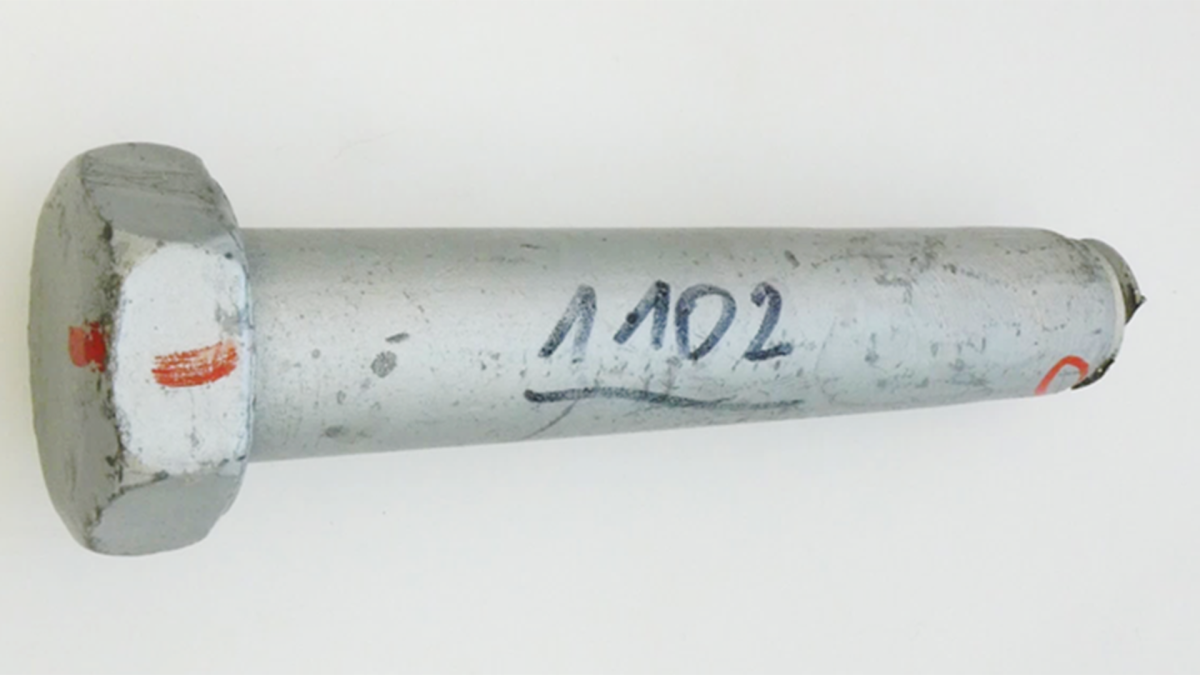
The laboratory of Würth Industrie Service was commissioned to examine a screw of strength class 10.9 that had fractured during assembly. According to the client, other screws from the batch were successfully installed with the same torque.
The laboratory also received the following information from the client:
- The shank was not evenly shaped above the point of fracture and showed marks of machining
- Side cracks were visually recognisable and were marked on the sample
The aim of the analysis was to determine the cause of the failure on the basis of the sample provided as well as to check whether there was a material or manufacturing defect that had caused or facilitated the failure
Failure hypothesis:
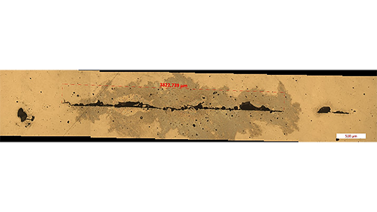
There were various possible causes for the failure: Part of the fracture surface was discoloured black. This typically occurs with quench cracks when the quenching oil can penetrate into the opened crack and leave residues there. Quench cracks often branch, which could have caused the subsidiary cracks.
However, it could also have been due to material defects already present in the semi-finished product. There was also a possibility of slag inclusions here.
The following tests were carried out in consultation with the client:
- Fracture surface analysis
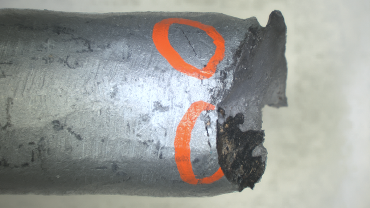
- EDX analysis
- Microstructure analysis
- Geometry test - shank diameter
The results are briefly summarised below:
- Torsional forced fracture, black area without fracture structures
- Slag residues detected, evidence of increased calcium concentration in the black area of the fracture surface
- Subsidiary cracks contain foreign phases
- Shank diameter 19.17 ± 0.02 mm, difference between the measurements very high, almost all measurements smaller than tolerance specification
Abridged interpretation / statement on the test results:
The test results suggested that the material defects found were already present in the primary material used. These defects reduce the load-bearing stress area of the screw and promote the formation of cracks. As a result, the effective strength of the screw was already exceeded with the tightening torque used.
Opinion:
The machining marks are an indication that the material defects were noticed during production and an attempt was made to remove them.
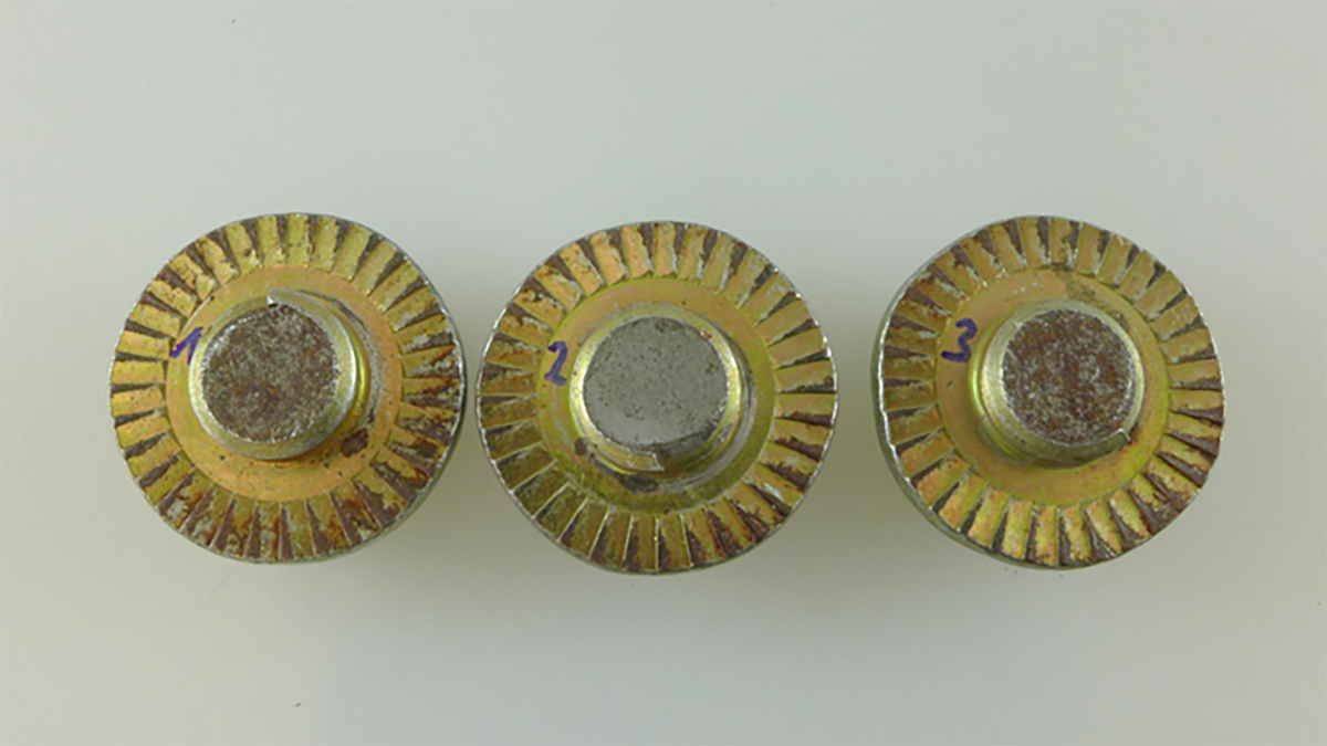
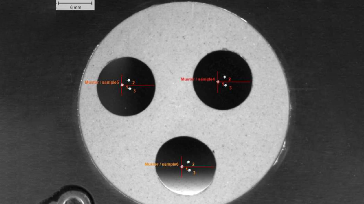
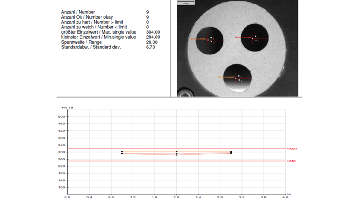
Background:
The laboratory of Würth Industrie Service was provided with three sets, each consisting of a screw and nut. All the screws had a fracture near the head. The subject of the examination was exclusively the screw.
The aim of the analysis was to determine the cause of the failure on the basis of the samples provided as well as to check whether there was a material or manufacturing defect that had caused or facilitated the failure.
Failure hypothesis:
It was assumed that faulty material properties such as hardness and microstructure were the reason for the failure. For example, excessive hardness (especially in the edge area) could explain the fracture without deformation. The possibility of incorrect case hardening could not be ruled out either.
The following tests were carried out in consultation with the client:
- Core hardness test HV10
- Hardness profile HV0.3 with regard to the presence of surface hardening
- Microstructure analysis
- Material analysis using a spark spectrometer
The results are briefly summarised below:
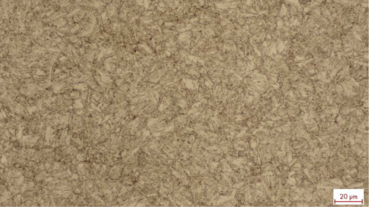
- Core hardness average value 296 HV10
- Surface hardening not present, evidence of inconspicuous hardness profile
- Microstructure of approx. 90% martensite, no carburisation or decarburisation detected, cracks in the thread base detected
- Alloy composition conforms to the normative specifications, no increased concentrations of embrittling elements detected
Abridged interpretation / statement on the test results:
All available results conformed to the normative specifications for screws of this property class. However, deep cracks were detected during the microstructure analysis in the thread, for which there are no standardised specifications regarding (in)admissibility. These cracks can result not only from the manufacture of the screws, but also, for example, from stresses during use.
In order to identify the cause of the fracture, we recommended further examination using a scanning electron microscope. At the time, this was carried out by an external partner laboratory and showed that the fracture surfaces tested were vibrational fractures with a relatively small residual fracture surface. This indicated that the clamp force was low at the time of the fracture. The clamp force of the assembly may not have been high enough or the screws may have loosened during operation.
We now have the capability to examine fracture surfaces with our own large-chamber scanning electron microscope and are happy to offer our customers this testing option. Please feel free to contact us to find out what other possibilities you can explore!
No macroscopic deformation recognisable in the area of the fracture (right in the image)
Fracture surface – light microscope
Fracture surface – SEM (scanning electron microscope)
Edge area fracture surface: Overview, transition from intercrystalline fractured edge to dimple fractured core, corrosion products mainly near the edge
Core area fracture surface: Ductile transcrystalline dimple structure
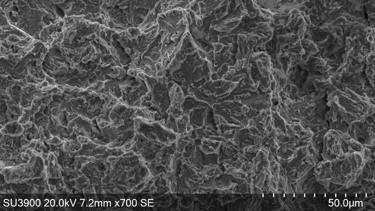
Area between edge and core (only distinctive in this form in places): Brittle transcrystalline fracture along secondary grain boundaries, occasional corrosion products
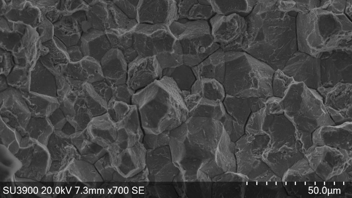
Edge area fracture surface: Brittle intercrystalline fracture, gaping grain boundaries and plastic residual deformation on the grain surfaces
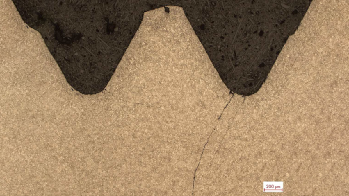
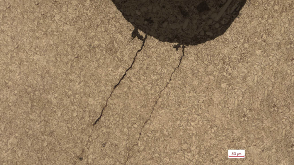
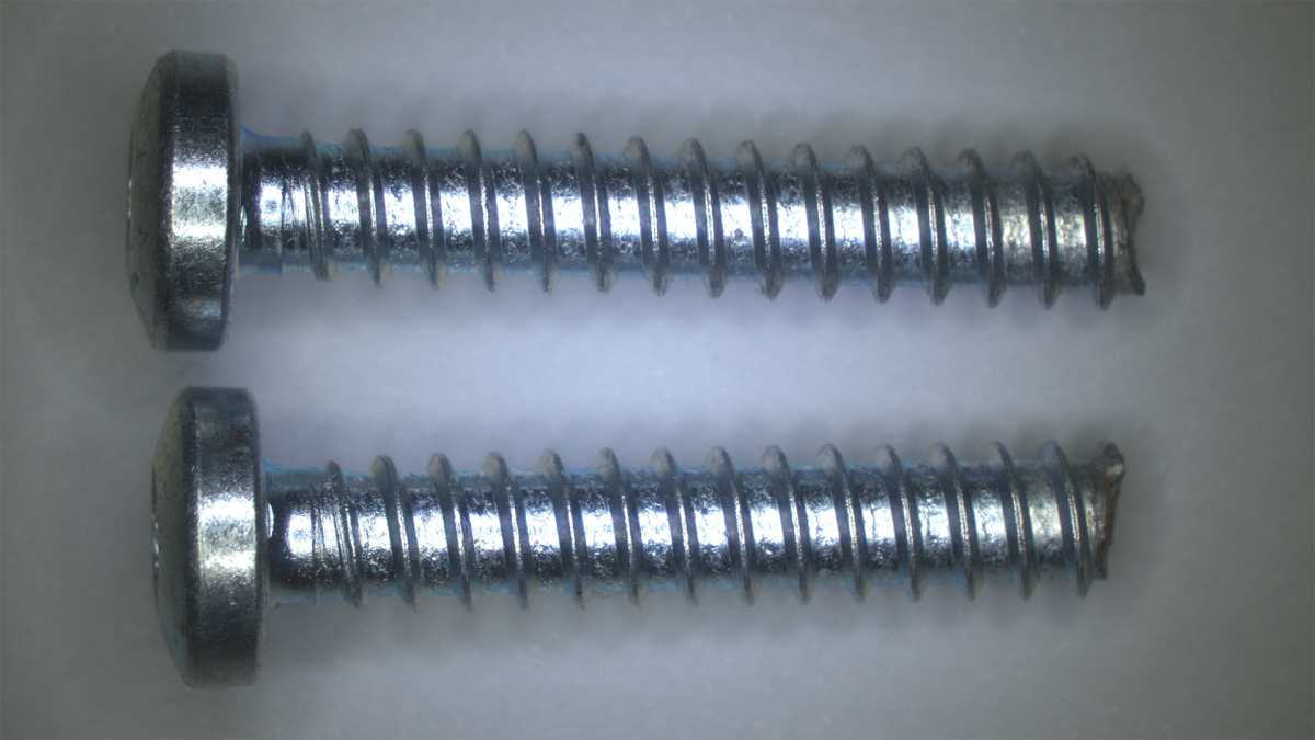
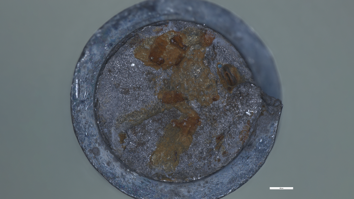
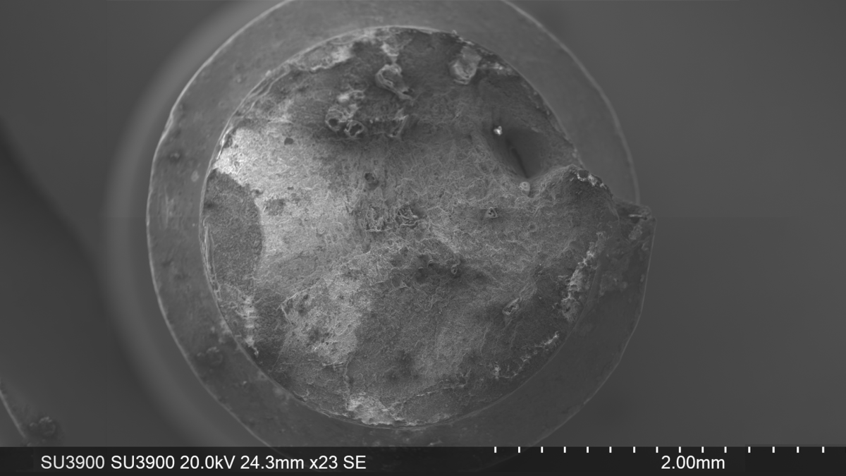
Background:
The laboratory of Würth Industrie Service was commissioned to examine two fractured drilling screws (only fragments with screw head available). Both samples showed obvious corrosion on the fracture surface. In addition, the client informed us that the parts were fractured after the assembly. Other screws were also fractured, but only two samples were provided for examination. The customer also described that further fractures could be triggered by exerting pressure on the screwed parts.
Failure hypothesis:
The information provided by the customer suggested that the drilling screws were fractured with a slight delay after assembly. There was no reliable, concrete data on the time of failure in relation to the time of assembly. Insufficient information is unfortunately a frequent problem when analysing failures, which is why the failure hypothesis must be based as far as possible on the information available. In this case, the hypothesis was that the edge area of the drilling screws had become brittle and cracks were formed. Due to the clamp force applied after assembly, these cracks grew after a certain time to form cracks through the entire screw. In the triggered fractures described, the growth in the crack was accelerated by the additional force applied. The embrittlement could have been due to an existing case hardening of the screws or also due to the influence of hydrogen. The latter hypothesis was supported by the existing traces of corrosion and also by the present galvanic coating, as both can be a source of hydrogen.
The following tests were carried out in consultation with the client:
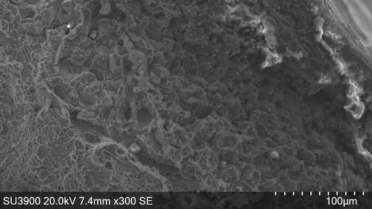
- Fracture surface analyses of the two fractured samples using SEM (scanning electron microscope)
The results are briefly summarised below:
- Similar fracture characteristics on both samples
- No deformation recognisable macroscopically, indicates brittle forced fracture
- Corrosion on the fracture surface, examination therefore only possible in non-corroded areas
- Difference between edge and core, sometimes also the area in between:
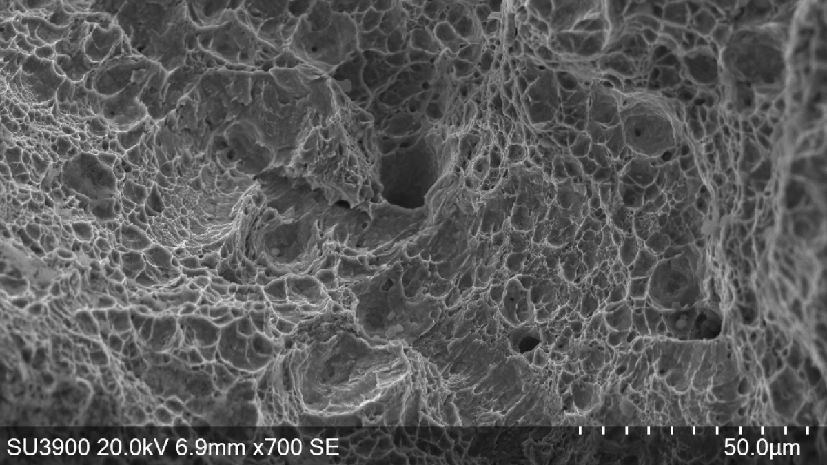
- Core area:
Mixed fracture of ductile dimple and brittle transcrystalline fracture components or purely ductile dimple fracture in the second sample - Intermediate area (only existing in places): partly ductile in dimple structure, partly brittle with transcrystalline fracture behaviour along the secondary grain boundaries or as a mixed fracture consisting of these parts
- Edge area:
Brittle intercrystalline fracture, gaping grain boundaries in places and in some cases plastic residual deformation recognisable on the grain surfaces
Abridged interpretation / statement on the test results:
The gaping grain boundaries and plastic residual deformation on the grain interfaces found in the edge area indicated a hydrogen-induced fracture. This was also consistent with the failure hypothesis, which was corroborated by this. It was not possible to say with certainty where the hydrogen ultimately came from, whether it was production-related during the coating process caused by the apparent corrosion or from other sources. The cracks, presumably originated in the brittle edge area, fractured the entire screw. The ductile areas in the core represented the remaining non-embrittled parts of the screw, which were no longer sufficiently strong to withstand the applied load.
Since the above-mentioned signs of hydrogen embrittlement were not identifiable everywhere, an additional influence of embrittlement due to the assumed case hardening could not be ruled out. Experience has shown that the fracture appearance was similar here, but without the above-mentioned signs. In order to analyse this theory in more detail, a microstructure analysis could also be carried out to prove case hardening. However, this was not commissioned in this case.
Geometric problems, such as a sharp-edged or over-rolled thread base, could also be factors that cause failure. However, the samples were not examined for this.
The Würth Industrie Service GmbH & Co. KG collects and processes the personal data provided in the form in order to process the requested request for you. Please note the mandatory fields in the forms. The legal basis for this processing, the absolutely necessary data, is Art. 6 para. 1 lit. b DSGVO, implementation of a pre-contractual measure. The processing of data voluntarily provided by you is carried out on the basis of Art. 6 para. 1 lit. f DSGVO. Thereafter, processing is permissible which is necessary to safeguard our legitimate interests. Our legitimate interest is to have contact with you, our customers, to improve our consulting quality and to be able to contact you more easily in case of possible queries. The data collected will only be stored by us for as long as is necessary to process your enquiry and to contact you. They are then deleted.
Supplementary data protection information, in particular regarding your rights to information, correction, deletion, restriction of processing, objection and complaint, can be found in our data protection declaration.